
Wiring Harness For A Pioneer Car Stereo
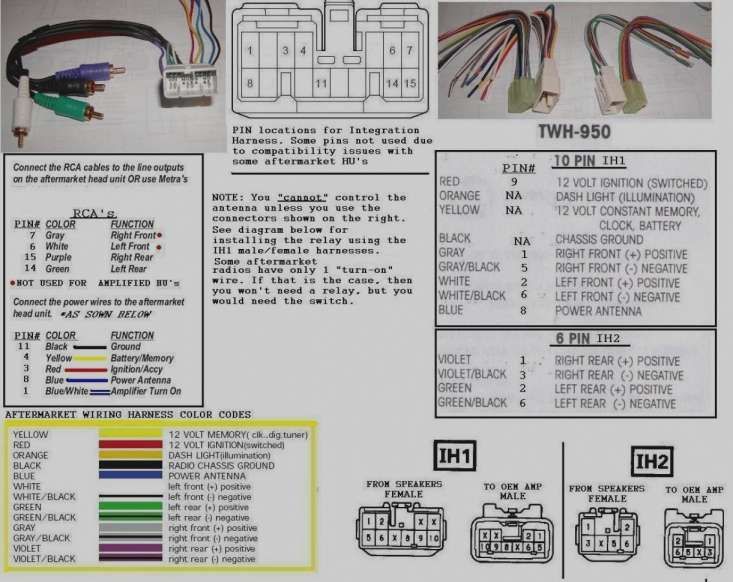
Understanding the wiring harness for your Pioneer car stereo is crucial whether you're installing a new unit, diagnosing audio problems, or simply deepening your understanding of your vehicle's electrical system. This guide provides an in-depth look at the components, functionalities, and troubleshooting aspects of a Pioneer car stereo wiring harness, empowering you to tackle common issues and modifications with confidence. We assume you have a basic understanding of automotive electrical systems and are comfortable using tools like wire strippers and multimeters.
Purpose of Understanding the Pioneer Wiring Harness
Why bother diving into the intricacies of a wiring harness? There are several compelling reasons:
- Installation and Upgrades: Successfully installing a new Pioneer stereo or upgrading existing components (like speakers or amplifiers) requires a solid understanding of how the harness connects to the vehicle's electrical system.
- Troubleshooting Audio Issues: Is your sound cutting out? Are speakers not working? The wiring harness is often the culprit, and knowing how to identify and test the wires can save you time and money on repairs.
- Preventing Damage: Incorrect wiring can lead to blown fuses, damaged components, or even electrical fires. Accurate wiring is paramount for safety.
- Customization and Modification: For those who like to customize their audio setup, understanding the wiring allows for integrating aftermarket accessories like subwoofers, equalizers, and Bluetooth adapters.
Key Specs and Main Parts of a Pioneer Wiring Harness
The Pioneer wiring harness is essentially a bundle of color-coded wires terminating in a connector (usually 16-pin, but can vary) designed to plug directly into the back of the stereo head unit. Here's a breakdown of the key components and specifications:
Main Power Wires:
- +12V Constant (Battery): Typically a yellow wire. This wire provides constant power to the stereo to retain memory (e.g., radio presets, clock settings) even when the ignition is off. It should be connected directly to the vehicle's battery positive terminal or a fused distribution block. This wire is *critical* for the radio to function and store settings.
- +12V Switched (Accessory/Ignition): Typically a red wire. This wire provides power to the stereo when the ignition is turned to the accessory or on position. It's often connected to a fuse in the car's fuse box that is only powered when the key is in the ACC or ON position.
- Ground: Typically a black wire. This wire provides the return path for the electrical current. It must be securely connected to a clean, unpainted metal part of the vehicle's chassis for proper grounding. Poor grounding can cause noise, distortion, and other electrical problems.
Speaker Wires:
Pioneer stereos typically support four speakers (front left, front right, rear left, rear right). Each speaker requires two wires: a positive (+) and a negative (-).
- Front Left: Typically white (positive) and white/black stripe (negative).
- Front Right: Typically gray (positive) and gray/black stripe (negative).
- Rear Left: Typically green (positive) and green/black stripe (negative).
- Rear Right: Typically purple (positive) and purple/black stripe (negative).
Other Important Wires:
- Remote Turn-On (Amplifier): Typically a blue or blue/white stripe wire. This wire provides a +12V signal to turn on external amplifiers when the stereo is powered on. It prevents the amplifier from being on constantly, draining the battery.
- Illumination: Typically an orange or orange/white stripe wire. This wire dims the stereo's display when the headlights are turned on. Connect this wire to the car's headlight circuit.
- Antenna Power: Typically a blue wire. This wire provides power to the car's power antenna, raising or lowering it when the radio is turned on.
- Mute: Sometimes a brown wire. This wire can be connected to a car phone system to mute the audio when a call is received. Less common in modern stereos.
- Steering Wheel Control: Often a combination of wires that connect to an adapter to allow the factory steering wheel controls to function with the aftermarket Pioneer unit. Requires a specific adapter that is often sold separately.
Understanding Wiring Harness Symbols and Color Codes
Wiring diagrams use standardized symbols and color codes to represent different components and connections. Lines represent wires, and their colors are indicated using abbreviations (e.g., Y for Yellow, R for Red, BK for Black). "GND" or a ground symbol indicates a ground connection. Fuse symbols depict fuses, and resistor symbols depict resistors. A circle with a 'A' in it often indicates an Amplifier. The crucial thing is consistent color coding. Pioneer usually uses the standard mentioned above.
A dotted line might indicate a shielded cable (used for RCA connections to reduce noise). A bold line often represents a power wire.
Understanding the color codes is particularly important for identifying the function of each wire. Always double-check the wiring diagram specific to *your* Pioneer stereo model.
How the Pioneer Wiring Harness Works
The wiring harness acts as the central nervous system of your car stereo. It takes power from the car's electrical system, distributes it to the stereo's internal components, and provides the necessary connections for audio output (speakers), signal input (antenna), and control functions (steering wheel controls).
When you turn the ignition key, the +12V Switched wire provides power to the stereo, turning it on. The +12V Constant wire maintains power to the memory functions. The stereo then processes audio signals from various sources (e.g., radio tuner, CD player, USB input) and sends the amplified signals to the speakers via the speaker wires. The amplifier turn-on wire activates external amplifiers, and the illumination wire dims the display when the headlights are on.
Real-World Use and Basic Troubleshooting
Here are some common issues and how to troubleshoot them using your understanding of the wiring harness:
- No Power to Stereo: Check the +12V Constant and +12V Switched wires with a multimeter to ensure they are receiving power. Also, check the ground connection. A blown fuse on either of these lines would also cause this problem.
- Stereo Loses Memory: Check the +12V Constant wire. If it's not receiving power, the stereo will lose its memory settings when the ignition is turned off.
- Speakers Not Working: Check the speaker wires for loose connections or damage. Use a multimeter to test the continuity of the speaker wires. Also, check the speaker impedance with a multimeter to make sure the speaker impedance matches the radio's requirements.
- Noise or Distortion: Check the ground connection. A poor ground can introduce noise into the audio signal. Also, check the RCA cables for damage.
- Amplifier Not Turning On: Check the Remote Turn-On wire. Ensure it's receiving a +12V signal when the stereo is powered on.
Important Tools: A multimeter, wire strippers, crimpers, and electrical tape or heat shrink tubing are essential for troubleshooting and repairs.
Safety Considerations
Working with automotive electrical systems can be dangerous. Always disconnect the negative terminal of the battery before working on any wiring. Identify the fuse box location and understand the wiring of your car. Be extremely careful when working with the +12V Constant wire, as it is always live and can cause a short circuit if accidentally grounded. Ensure all connections are properly insulated to prevent shorts. Always double-check your wiring before reconnecting the battery.
High-Risk Components: The +12V Constant wire and the amplifier are the most risky components. Exercise extreme caution when working with these wires to prevent electrical shocks or damage to your vehicle.
By understanding the Pioneer car stereo wiring harness, you can confidently tackle installations, upgrades, and troubleshooting, ensuring a safe and enjoyable audio experience in your vehicle.
We have a sample Pioneer wiring diagram available for download. It’s a generic diagram, so always compare it with the diagram specific to your Pioneer unit model before making any connections.