Wiring Harness For Aftermarket Radio
Replacing a factory radio with an aftermarket unit is a common upgrade, but navigating the wiring can feel like deciphering an alien language. This article provides a detailed breakdown of wiring harnesses used for aftermarket radio installations, acting as your go-to guide for successful and safe installations. Whether you're troubleshooting a malfunctioning system, upgrading your sound, or simply expanding your automotive knowledge, understanding these diagrams is crucial. Consider this your roadmap to audio enlightenment!
Purpose of Understanding Wiring Harness Diagrams
Wiring harness diagrams are essential for several reasons:
- Installation: They provide the necessary information to correctly connect your aftermarket radio to your car's electrical system, ensuring proper functionality.
- Troubleshooting: When issues arise (no sound, radio won't turn on, etc.), the diagram allows you to systematically check connections and identify potential problems like shorts or open circuits.
- Repair: If a wire becomes damaged or disconnected, the diagram helps you locate the correct replacement and restore the connection.
- Customization: Planning to add amplifiers, subwoofers, or other audio components? The diagram shows you where to tap into the existing system.
- Learning: Grasping how these systems operate enhances your understanding of automotive electrical systems in general.
Key Specifications and Main Parts of an Aftermarket Radio Wiring Harness
Before diving into a diagram, let's define some critical components and specifications:
- Harness Adapter: This is the interface between your car's factory wiring and the aftermarket radio. It prevents you from having to cut or splice the original wires. The adapter typically has two connectors: one that plugs into the car's factory harness and another that plugs into the aftermarket radio. These are often vehicle specific.
- Power Wire (Typically Yellow): Provides constant 12V power to the radio, used for memory retention (station presets, clock settings, etc.). This is a critical wire for maintaining your radio's settings.
- Ground Wire (Typically Black): Connects the radio to the vehicle's chassis ground, providing a return path for the electrical current. A solid ground is essential for proper operation and to prevent noise.
- Accessory Wire (Typically Red): Provides switched 12V power, meaning the radio only turns on when the ignition is on. This prevents the radio from draining the battery when the car is off.
- Speaker Wires: Typically eight wires (four pairs), connecting to the front left, front right, rear left, and rear right speakers. Each pair consists of a positive (+) and negative (-) wire.
- Antenna Wire: Connects to the car's antenna, allowing the radio to receive radio signals.
- Remote Turn-On Wire (Typically Blue): Used to turn on external amplifiers. When the radio is powered on, this wire sends a 12V signal to activate the amp.
- Illumination Wire (Typically Orange or Orange/White): Dims the radio's display when the headlights are turned on.
- Reverse Wire (Typically Purple/White): Activates the backup camera display when the car is in reverse (if your radio and car support this feature).
Wire Gauge: The thickness of the wire. Typically, speaker wires are 18-22 gauge, while power and ground wires are often 16-18 gauge. Using the correct gauge is important to handle the current load.
Fuse Rating: The fuse protects the radio from overcurrent situations. The fuse rating should match the radio's specifications. Using a higher rated fuse can be dangerous and cause damage.
Understanding Wiring Diagram Symbols and Color Codes
Wiring diagrams use a standardized set of symbols and color codes to represent different components and connections. Here's a breakdown:
Lines:
- Solid Lines: Represent wires.
- Dashed Lines: Might indicate shielded wires or connections that are not always present.
- Arrows: Indicate the direction of current flow.
Colors:
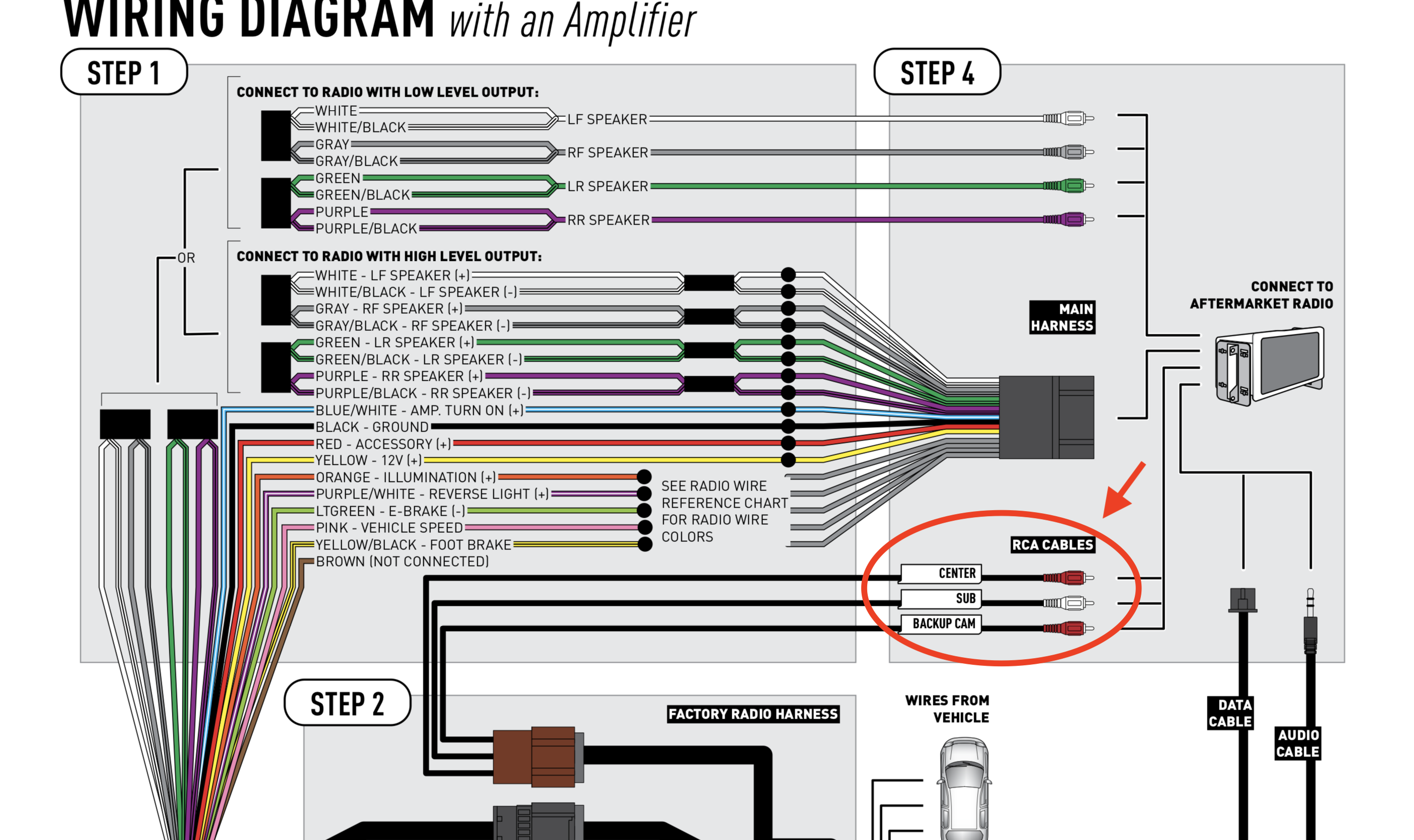
Color codes are crucial for identifying wires. While standards exist, some variations are possible. Here are the most common:
- Black: Ground
- Red: Switched 12V (Accessory)
- Yellow: Constant 12V (Battery)
- White: Typically front left speaker (+)
- White/Black Stripe: Typically front left speaker (-)
- Gray: Typically front right speaker (+)
- Gray/Black Stripe: Typically front right speaker (-)
- Green: Typically rear left speaker (+)
- Green/Black Stripe: Typically rear left speaker (-)
- Purple: Typically rear right speaker (+)
- Purple/Black Stripe: Typically rear right speaker (-)
- Blue: Remote Turn-On
- Orange or Orange/White: Illumination
- Purple/White: Reverse
Connectors: Wiring diagrams use symbols to represent connectors (where wires plug into each other). Pay close attention to the connector pinout (the arrangement of wires within the connector). Mismatched pinouts are a common source of installation issues.
Icons:
- Fuse: The zig-zag line.
- Ground: Represented by the downward arrow.
How It Works: Tracing the Electrical Path
The fundamental principle is simple: the radio needs power (both constant and switched), ground, and connections to the speakers and antenna. The wiring harness facilitates these connections without altering the car's original wiring.
Here's a simplified explanation of the signal flow:
- Power: The constant 12V (yellow wire) keeps the radio's memory alive. The switched 12V (red wire) turns the radio on and off with the ignition. Both wires are protected by fuses.
- Ground: The black wire provides a return path for the electrical current, completing the circuit.
- Audio Signal: The radio sends amplified audio signals through the speaker wires to each speaker.
- Control Signals: The illumination wire dims the display, and the reverse wire activates the backup camera (if applicable). The remote turn-on wire signals amplifiers to power on.
The harness adapter acts as an intermediary, routing these signals from the car's wiring to the corresponding connections on the aftermarket radio. Careful matching of wires based on function and color is essential.
Real-World Use: Basic Troubleshooting Tips
Encountering problems after installation is common. Here are some troubleshooting tips using the wiring diagram:
- No Power: Check the fuses on both the radio and the car. Verify the constant 12V and switched 12V wires are receiving power using a multimeter. Ensure the ground connection is secure.
- No Sound: Check the speaker wire connections. Make sure the positive and negative wires are correctly connected to each speaker. Verify the radio's fader and balance settings are properly adjusted.
- Radio Won't Turn Off: The accessory wire might be connected to a constant 12V source instead of a switched source. Use the wiring diagram to identify the correct wire.
- Humming or Static: Could be a grounding issue. Ensure the radio is properly grounded to a clean metal surface. Check for loose or corroded connections.
- Remote Turn-On Issues: Check the remote turn-on wire connection to the amplifier. Verify the amplifier is properly grounded.
Safety Considerations
Working with automotive electrical systems can be dangerous. Observe the following precautions:
- Disconnect the Negative Battery Terminal: Always disconnect the negative battery terminal before working on any electrical components. This prevents accidental shorts and electrical shocks.
- Use Proper Tools: Use insulated tools to prevent shorts.
- Never Bypass Fuses: Fuses are safety devices designed to protect the system from overcurrent. Never replace a fuse with a higher rated one or bypass it altogether.
- Be Careful with the Airbag System: Some wiring may be near the airbag system. Refer to the car's service manual for proper handling procedures.
High-Risk Components: The power wires (constant and switched) and the ground wire carry significant current. Handle these wires with extra care.
We have a detailed wiring diagram that can aid you in understanding how these circuits connect. This diagram is specifically built with common aftermarket radio wiring configurations in mind.
You can download the wiring diagram from our website: [hypothetical link to download].