
Wiring Harness For Blower Motor Resistor
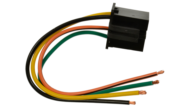
Let's dive into the often-overlooked but crucial wiring harness for your blower motor resistor. This component is responsible for controlling the speed of your car's blower fan, which in turn dictates how much air flows through your vents. Understanding its wiring is essential for diagnosing HVAC problems, performing repairs, and even undertaking certain vehicle modifications. Forget taking it to the shop! With a little know-how, you can troubleshoot and potentially fix issues yourself. And don't worry, we've got a detailed wiring diagram available for download at the end of this article to make things even easier.
Why This Wiring Diagram Matters
The blower motor resistor wiring harness is the nerve center for your vehicle's climate control. A malfunctioning resistor can lead to several frustrating issues:
- No fan at all: The blower motor refuses to spin, leaving you with stifling heat or frigid air, depending on the season.
- Fan works only on one speed: Typically, the highest setting works, while lower speeds are non-functional. This is a classic sign of a burned-out resistor.
- Erratic fan operation: The fan speed fluctuates randomly, indicating a faulty resistor or loose connection.
Having access to the wiring diagram empowers you to:
- Diagnose the problem: Identify whether the issue lies within the resistor itself, the wiring harness, the blower motor, or the control switch.
- Perform repairs: Replace damaged wiring, repair corroded connectors, or replace the resistor itself with confidence.
- Understand your vehicle's electrical system: Gain a deeper understanding of how your car's HVAC system functions.
- Plan modifications: Whether you’re adding an aftermarket climate control system or performing other electrical upgrades, a clear understanding of the existing wiring is essential.
Key Specs and Main Parts
Let's break down the key components and their specifications:
Blower Motor Resistor
This is the heart of the speed control system. It consists of a series of resistors, each designed to drop a specific amount of voltage. By routing power through different combinations of resistors, the control switch effectively regulates the voltage supplied to the blower motor, thereby controlling its speed.
Key Specs:
- Resistance values: Each resistor in the array will have a specific resistance value (measured in ohms - Ω), determining the voltage drop for each speed setting.
- Power rating: The resistor must be able to dissipate the heat generated by the current flowing through it. The power rating is measured in watts (W).
- Number of speeds: The resistor controls the number of available fan speeds (e.g., low, medium-low, medium-high, high).
Wiring Harness
This is the bundle of wires that connects the resistor to the blower motor, the control switch, and the vehicle's power source. It's crucial that these wires are in good condition, free from corrosion, and properly connected.
Key Specs:
- Wire gauge: The thickness of the wires, which determines how much current they can safely carry. Common gauges are 16 AWG or 18 AWG.
- Wire insulation: The type of insulation used to protect the wires from short circuits and environmental factors. Common types include PVC and XLPE.
- Connector type: The type of connectors used to join the wires to the resistor, blower motor, and control switch. Common types include push-on connectors and blade connectors.
Blower Motor
The motor itself draws current and spins the fan, creating airflow. It's directly powered through the resistor, so its electrical health is essential.
Key Specs:
- Voltage: Typically 12V DC in most vehicles.
- Current draw: This varies depending on the speed.
Control Switch
The switch is what you use to select the desired fan speed, sending signals to the resistor.
Understanding the Wiring Diagram Symbols
Wiring diagrams use standardized symbols to represent components and connections. Here's a brief overview:
- Solid Lines: Represent wires. The thickness may indicate the wire gauge (thicker lines for higher current).
- Dashed Lines: Often indicate a ground connection or a shielded wire.
- Circles: Represent connectors or junctions.
- Rectangles: Represent components like the resistor, blower motor, and control switch.
- Ground Symbol (three horizontal lines decreasing in length): Indicates a connection to the vehicle's chassis ground.
- Resistor Symbol (zigzag line): Represents a resistor.
- Motor Symbol (circle with an "M" inside): Represents an electric motor.
Color Codes: Wiring diagrams also use color codes to identify wires. Common colors include:
- Red: Typically used for power (positive +12V).
- Black: Typically used for ground.
- Other Colors (e.g., Blue, Green, Yellow, White): Used for signal wires or other specific functions. The diagram will usually have a legend explaining the color codes.
It's absolutely crucial to consult the specific wiring diagram for your vehicle's make, model, and year, as wire colors and component locations can vary significantly.
How It Works: A Simple Explanation
The blower motor resistor system is a relatively simple voltage divider circuit. The control switch selects which resistor (or combination of resistors) to use in the circuit. Here's how it typically works:
- Power (typically +12V) is supplied from the vehicle's battery through a fuse or circuit breaker to the blower motor resistor.
- The control switch determines which path the current will take through the resistor.
- For the highest fan speed, the current usually bypasses the resistors altogether, providing the full 12V directly to the blower motor.
- For lower speeds, the current flows through one or more resistors, dropping the voltage before it reaches the blower motor. The more resistance in the circuit, the lower the voltage, and the slower the fan spins.
- The current then flows from the blower motor to ground, completing the circuit.
Think of it like a water hose. The full voltage is like a wide-open hose with a strong flow. Resistors are like constricting the hose – limiting the flow (voltage) and reducing the strength of the stream (fan speed).
Real-World Use: Basic Troubleshooting Tips
Here are some basic troubleshooting tips you can use with the wiring diagram:
- No Fan at All: Check the fuse for the blower motor. If the fuse is good, use a multimeter to check for voltage at the blower motor resistor. If there's no voltage, the problem may lie in the wiring between the fuse and the resistor or the control switch. If there is voltage, the resistor itself may be faulty or the blower motor may be dead.
- Fan Works Only on High: This is a classic sign of a burned-out resistor. The high speed bypasses the resistors, so it still works. Use a multimeter to check the resistance of each resistor in the array. If any of them are open (infinite resistance), the resistor needs to be replaced.
- Erratic Fan Operation: Check the connectors on the wiring harness for corrosion or loose connections. Clean the connectors with electrical contact cleaner and ensure they are securely fastened. Also, check for any damaged or frayed wires.
Always disconnect the battery before working on any electrical components to prevent short circuits and potential damage.
Safety First! Highlighting Risky Components
The blower motor resistor can get very hot during normal operation. This is because it's dissipating electrical energy as heat. Therefore, it's crucial to:
- Allow the resistor to cool down before handling it.
- Avoid touching the resistor while the blower motor is running.
- Ensure the resistor is properly mounted to a heat sink (typically a metal plate) to dissipate heat.
- Never bypass the resistor for extended periods, as this can damage the blower motor or other electrical components.
Furthermore, always be careful when working with automotive electrical systems. Disconnect the negative battery cable before beginning any work to avoid accidental shorts and potential electrical shock. Use proper safety equipment, such as insulated tools and safety glasses.
Armed with this information and the wiring diagram, you're well-equipped to tackle blower motor resistor problems. Remember to consult the specific diagram for your vehicle and always prioritize safety.
Ready to get started? Click the link below to download the detailed wiring diagram. [Download Wiring Diagram Link Here (Placeholder)]