Wiring Harness For Crankshaft Position Sensor
Let's dive into the crucial world of crankshaft position (CKP) sensor wiring harnesses. Understanding this often-overlooked component is essential for diagnosing engine problems, performing modifications, and even just deepening your overall automotive knowledge. This article aims to provide a clear and practical understanding of CKP sensor wiring harnesses, assuming you have some existing mechanical aptitude. We'll break down the purpose, components, functionality, troubleshooting, and safety aspects.
Purpose of the CKP Sensor Wiring Harness
The wiring harness for the crankshaft position sensor serves a vital role: it provides the electrical pathway between the CKP sensor and the engine control unit (ECU). The CKP sensor monitors the position and speed of the crankshaft. This information is absolutely critical for the ECU to accurately control fuel injection timing and ignition timing. Without a functioning CKP sensor and a reliable wiring harness, your engine simply won't run correctly, if at all.
This diagram matters for several reasons:
- Repairs: Identifying breaks, shorts, or corrosion in the harness is essential for fixing engine problems.
- Diagnostics: Pinpointing wiring issues can save you time and money when troubleshooting a faulty CKP sensor.
- Modifications: When swapping engines or ECUs, understanding the wiring allows for proper integration.
- Learning: Gain a deeper understanding of how your engine management system works.
Key Specs and Main Parts
A typical CKP sensor wiring harness is relatively simple, but attention to detail is crucial. The main components include:
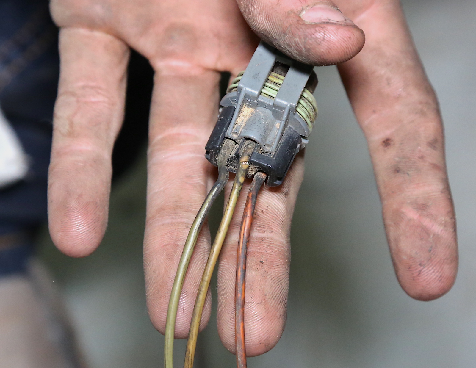
- CKP Sensor Connector: This connects directly to the CKP sensor itself. The connector type will vary depending on the vehicle and sensor design. Common types include 2-pin and 3-pin connectors.
- Wiring: Typically, the harness will consist of two or three wires (depending on the sensor type) that are appropriately gauged to handle the low-voltage signals. These wires are usually color-coded for easy identification.
- Connector to ECU/Main Harness: This connects the CKP sensor wiring into the vehicle's main wiring harness, which ultimately leads to the ECU. This connection may be a single multi-pin connector or individual wire splices.
- Ground Wire (if applicable): Some CKP sensors require a dedicated ground wire for accurate readings. This wire ensures a stable and reliable ground connection.
- Protective Sheathing: The wiring is typically protected by a heat-resistant and abrasion-resistant sheathing (e.g., corrugated tubing or electrical tape) to prevent damage from engine heat, movement, and contaminants.
Key specifications to consider include:
- Wire Gauge: The thickness of the wires, typically ranging from 18 to 22 AWG (American Wire Gauge).
- Wire Insulation Type: The type of insulation used to protect the wires, such as PVC (Polyvinyl Chloride) or XLPE (Cross-Linked Polyethylene). XLPE is typically more heat resistant.
- Connector Type: The specific type of connector used for the CKP sensor and ECU connections.
- Operating Voltage: Typically 5V or 12V, depending on the CKP sensor and ECU design.
Symbols and Color Codes
Understanding the symbols and color codes used in wiring diagrams is crucial for accurate troubleshooting and repairs. While specific conventions may vary slightly between manufacturers, some common standards apply.
- Lines: Represent wires. Solid lines indicate direct connections, while dashed lines may indicate shielded wires or connections through a relay or other device.
- Colors: Each wire is typically identified by a color code. Common colors include:
- Red (R): Often used for power.
- Black (B): Usually indicates ground.
- Yellow (Y): Signal wire.
- Green (G): Signal wire or ground.
- Blue (BL): Signal wire.
- White (W): Signal wire.
- Icons: Represent components such as sensors, connectors, and the ECU. These icons are standardized, but it's always best to consult the specific vehicle's wiring diagram for accurate identification.
When reading a wiring diagram, pay close attention to the pin numbers on the connectors. This will help you identify the correct wire and its corresponding function.
How It Works
The CKP sensor generates a signal that reflects the crankshaft's position. There are two main types of CKP sensors:
- Magnetic Inductive Sensors: These sensors contain a coil of wire and a magnet. As the crankshaft rotates, a toothed wheel (reluctor ring) passes by the sensor, disturbing the magnetic field. This induces a voltage signal in the coil, which is then sent to the ECU.
- Hall Effect Sensors: These sensors use a semiconductor chip to detect changes in a magnetic field. As the toothed wheel rotates, it interrupts the magnetic field, causing the sensor to output a digital signal (on/off) to the ECU.
The wiring harness transmits this signal to the ECU. The ECU uses this information to determine the precise position of the crankshaft and calculate the optimal timing for fuel injection and ignition. A faulty wiring harness can disrupt this signal, causing misfires, rough idling, stalling, or a complete engine shutdown. The ECU monitors the signal coming from the CKP sensor, and if it detects a problem (e.g., no signal, intermittent signal, or out-of-range signal), it will typically store a diagnostic trouble code (DTC) in its memory.
Real-World Use - Basic Troubleshooting Tips
Here are some basic troubleshooting tips for diagnosing CKP sensor wiring harness issues:
- Visual Inspection: Carefully inspect the wiring harness for any signs of damage, such as cuts, abrasions, melted insulation, or corrosion. Pay close attention to the connectors and areas where the harness is routed near hot or moving parts.
- Continuity Test: Use a multimeter to check the continuity of each wire in the harness. Disconnect the harness from both the CKP sensor and the ECU (or main harness) before testing. A lack of continuity indicates a break in the wire.
- Voltage Test: Check the voltage at the CKP sensor connector with the ignition on. Consult the vehicle's service manual for the correct voltage specifications. A lack of voltage may indicate a problem with the power supply to the sensor.
- Resistance Test: Check the resistance of the CKP sensor itself. A faulty sensor can sometimes mimic a wiring harness issue. Again, consult the service manual for the correct resistance range.
- Scan Tool Diagnostics: Use an OBD-II scan tool to check for any DTCs related to the CKP sensor. These codes can provide valuable clues about the nature of the problem. Common codes include P0335 (Crankshaft Position Sensor A Circuit) and P0336 (Crankshaft Position Sensor A Circuit Range/Performance).
- Wiggle Test: With the engine running (if possible), gently wiggle the wiring harness and connectors. If the engine stumbles or stalls, it may indicate a loose connection or a break in the wire.
Safety Considerations
Working with electrical systems can be dangerous. Always follow these safety precautions:
- Disconnect the Battery: Before working on any electrical components, disconnect the negative terminal of the battery to prevent accidental shorts or electrical shocks.
- Use Proper Tools: Use insulated tools specifically designed for automotive electrical work.
- Avoid Working in Wet Conditions: Never work on electrical systems in wet or damp conditions.
- Be Aware of High-Voltage Components: While the CKP sensor itself operates on low voltage, be aware of other high-voltage components in the engine compartment, such as the ignition coil and spark plug wires. Avoid touching these components when the engine is running.
- Consult the Service Manual: Always consult the vehicle's service manual for specific wiring diagrams, testing procedures, and safety precautions.
Remember: Some electrical components, particularly within the ECU itself, are extremely sensitive to static electricity. Ground yourself properly before handling any electronic components to avoid damaging them.
By understanding the principles of CKP sensor wiring harnesses, you can effectively diagnose and repair engine problems, perform modifications, and expand your automotive knowledge. A reliable wiring harness is the unsung hero of your engine's control system. Take the time to understand it, and you'll be well-equipped to tackle a wide range of automotive challenges.
We have prepared a detailed CKP wiring harness diagram for your reference. The link is available for you to download here.