
Wiring Harness For Pioneer Car Stereo
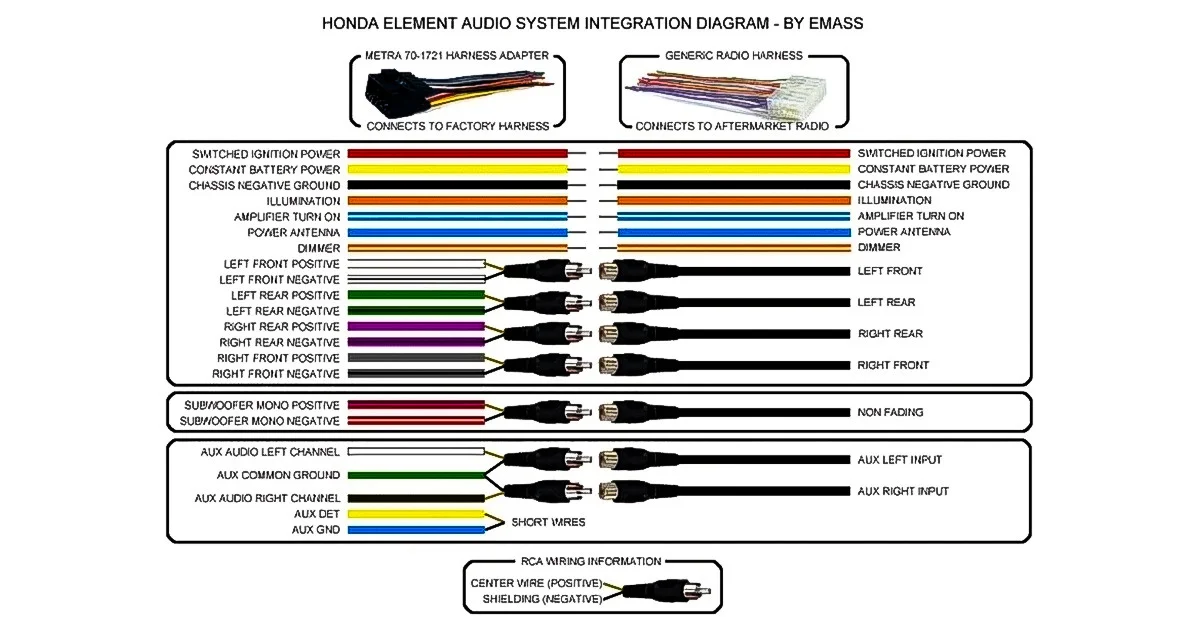
Alright, let's dive into the fascinating, and sometimes frustrating, world of wiring harnesses for Pioneer car stereos. Whether you're upgrading your head unit, diagnosing a pesky audio issue, or just want to understand how all those colorful wires connect your stereo to your car, understanding the wiring harness is absolutely crucial. This guide aims to demystify the Pioneer wiring harness, providing you with the knowledge to confidently tackle your next car audio project. We have included an option to download the wiring diagram file to make things easier.
Purpose of the Wiring Diagram
Why bother learning about this? Well, a wiring diagram is your roadmap to a successful installation and a crucial tool for troubleshooting. It's far more than just connecting wires by matching colors (though that's a good starting point!). A proper understanding allows you to:
- Safely install a new Pioneer head unit: Avoiding blown fuses, fried electronics, or even worse, electrical fires.
- Diagnose audio problems: Pinpointing whether the issue is with the stereo, the speakers, the wiring, or the car's electrical system.
- Modify your system: Adding amplifiers, subwoofers, or other accessories without causing damage or interference.
- Learn about automotive electrical systems: Gaining a deeper understanding of how your car's electrical components interact.
- Repair damaged wiring: Effectively replace damaged or deteriorated wires, ensuring proper functionality.
Key Specs and Main Parts of a Pioneer Wiring Harness
A typical Pioneer wiring harness consists of a standardized connector that plugs directly into the back of the head unit and is often connected to a universal car stereo harness via crimp connectors or solder.
Main Components and Their Functions:
- Power Wires: These are the lifelines of your stereo.
- Ground Wire (Black): Provides the return path for the electrical current. A good, clean ground is absolutely essential for proper stereo operation. Poor grounding is a common source of noise and other problems.
- +12V Constant (Yellow): Provides power to the stereo to retain memory functions (like radio presets and clock settings) even when the car is turned off. It's constantly powered from the battery.
- +12V Switched (Red): Provides power to turn the stereo on and off when the ignition is switched. This is often referred to as the Accessory wire.
- Speaker Wires: These carry the audio signal from the head unit to the speakers. They are usually twisted pairs of wires.
- Front Left (+/-)
- Front Right (+/-)
- Rear Left (+/-)
- Rear Right (+/-)
- Control/Signal Wires: These wires handle various control and signaling functions.
- Remote Turn-On (Blue/White): Used to activate external amplifiers when the head unit is powered on. This signal wire prevents your amp from constantly draining your battery.
- Illumination (Orange/White): Dims the stereo display when the headlights are turned on. This can also be a straight orange wire in some models.
- Antenna Power (Blue): Provides power to the car's power antenna or an amplified antenna.
- Steering Wheel Control (SWC): Allows the stereo to be controlled using the car's steering wheel controls (requires a separate adapter in most cases).
- Mute (Brown or Black/Yellow): Designed to mute the stereo during calls with a car kit
Understanding Wiring Diagram Symbols
A wiring diagram isn't just a bunch of lines and colors; it's a symbolic representation of the electrical circuit. Understanding these symbols is critical for interpreting the diagram correctly.
- Solid Lines: Represent wires. The thickness of the line doesn't usually indicate wire gauge in these diagrams.
- Dashed Lines: May indicate shielded wiring or wiring that is optional or only present in certain configurations.
- Color Codes: Each wire is typically labeled with a color code (e.g., "YEL" for Yellow, "RED" for Red, "BLK" for Black, "BLU" for Blue, "GRN" for Green, "WHT" for White, "ORG" for Orange). These color codes are crucial for identifying the correct wires.
- Connectors: Represented by various shapes, often rectangles or circles with pins inside. They show where wires connect and disconnect.
- Fuses: Represented by a wavy line inside a rectangle. They protect the circuit from overcurrent.
- Ground Symbol: Usually represented by a series of horizontal lines getting progressively shorter, indicating a connection to the car's chassis.
How a Pioneer Car Stereo Wiring Harness Works
The wiring harness acts as the central nervous system of your car stereo system. It provides the necessary power for the head unit to operate, transmits audio signals to the speakers, and allows for control and communication with other components.
Here's a simplified explanation:
- Power Delivery: The +12V Constant wire ensures that the stereo retains its memory, while the +12V Switched wire tells the stereo when to turn on and off with the ignition.
- Audio Transmission: The speaker wires carry the amplified audio signal from the head unit's internal amplifier to each of the speakers in your car.
- Control and Signaling: The Remote Turn-On wire signals external amplifiers to power on, the Illumination wire dims the display at night, and the Steering Wheel Control wire allows you to control the stereo using your car's steering wheel buttons.
- Grounding: The ground wire completes the circuit, allowing current to flow back to the car's battery. A poor ground will cause lots of issues.
Real-World Use: Basic Troubleshooting Tips
When things go wrong, the wiring harness is often the culprit. Here are a few troubleshooting tips:
- No Power: Check the fuses (both in the head unit and in the car's fuse box). Ensure the +12V Constant and +12V Switched wires are receiving power using a multimeter. Verify a good ground connection.
- No Sound: Check the speaker connections. Ensure the speaker wires are properly connected to both the head unit and the speakers. Make sure that speaker wires do not touch metal, grounding out. Test with a known good speaker.
- Stereo Turns Off Randomly: Could be a loose connection, a faulty ground, or an overloaded circuit. Check all wiring connections and the ground wire. This issue can sometimes be caused by a failing head unit.
- Excessive Noise: Often caused by a poor ground. Ensure the ground wire is securely connected to a clean, bare metal surface. Check speaker wires for damage.
- Steering Wheel Controls Not Working: Verify that the steering wheel control adapter is properly installed and programmed.
Safety: Highlighting Risky Components
Working with automotive electrical systems can be dangerous if proper precautions aren't taken.
- Battery: Always disconnect the negative terminal of the battery before working on any electrical components. This will prevent accidental short circuits and potential damage.
- Airbags: Be extremely careful when working near airbag modules. Accidental activation can cause serious injury. Consult your car's service manual for proper airbag disabling procedures.
- Wiring: Never cut or splice wires without understanding their function. Improper wiring can lead to blown fuses, damaged components, or even electrical fires.
- Short Circuits: Be vigilant in preventing short circuits. Ensure that all connections are properly insulated and that no bare wires are exposed.
- Tools: Always use insulated tools when working on electrical systems.
The information in this article will provide insight into how your Pioneer radio wiring harness works, but it is not a substitute for the official wiring diagram. Remember to always consult your vehicle's service manual and the specific documentation for your Pioneer head unit before beginning any installation or repair work. These documents will provide specific wiring information and any pertinent warnings.
We have the wiring diagram file for download. You can download it by clicking here.