Wiring Harness For Trailer Brake Controller
So, you're looking to understand the wiring harness for a trailer brake controller, eh? Whether you're tackling a repair, installing a new unit, or simply aiming to demystify the electrical system of your towing setup, this knowledge is invaluable. We're going to break down the typical trailer brake controller wiring diagram like I would for a fellow mechanic – clearly, concisely, and with the insights you need to get the job done right.
Purpose
Understanding the wiring diagram for your trailer brake controller isn't just about following instructions; it's about comprehending the system. This understanding empowers you to:
- Diagnose problems: Identify faulty wiring, blown fuses, or a malfunctioning controller.
- Perform repairs: Replace damaged wires, connectors, or components with confidence.
- Install new controllers: Ensure a proper and safe installation, avoiding common pitfalls.
- Customize your setup: Add features like manual override switches or monitor systems.
- Learn and expand your knowledge: Deepen your understanding of automotive electrical systems.
Without a solid grasp of the wiring, you're essentially working blind, relying solely on luck. This can lead to frustration, wasted time, and, more importantly, potentially dangerous situations.
Key Specs and Main Parts
The trailer brake controller wiring harness connects the controller to the vehicle's electrical system and the trailer's braking system. It typically involves several wires, each with a specific function. Here are the key components and their typical specifications:
- Brake Controller Unit: This is the brains of the operation, sensing the vehicle's deceleration and applying the appropriate amount of braking force to the trailer. Different controllers support different types of braking systems (electric, electric-over-hydraulic).
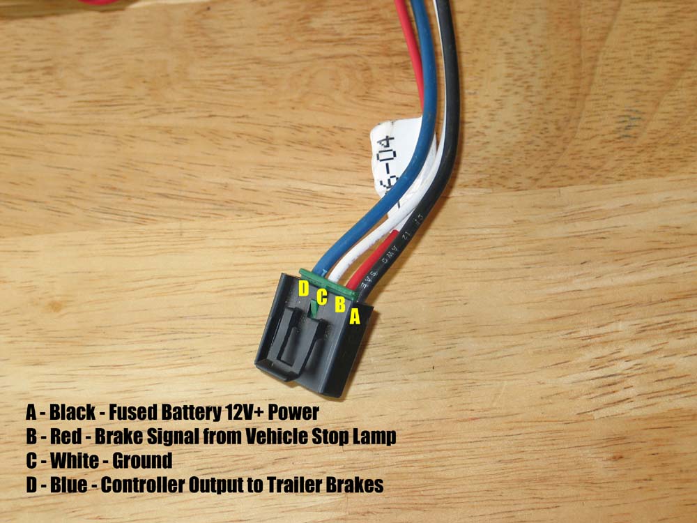
- Power Wire (typically Red or Black): This wire connects directly to the vehicle's battery (usually via a circuit breaker or fuse) and provides the necessary power to operate the controller. It's typically a heavy gauge wire (10 or 12 AWG) to handle the current draw. Voltage is typically 12V DC.
- Ground Wire (typically White): This wire provides a return path for the electrical current and is connected to the vehicle's chassis ground. Like the power wire, it should be a sufficient gauge to handle the current.
- Brake Signal Wire (typically Blue): This wire connects to the vehicle's brake light switch circuit. When the vehicle's brakes are applied, this signal triggers the controller to activate the trailer brakes. The signal should be 12V DC when the brake pedal is pressed.
- Output Wire to Trailer Brakes (typically Blue, matching the brake signal): This wire carries the voltage from the brake controller to the electric brakes on the trailer. The voltage is variable, controlled by the brake controller based on the vehicle's deceleration.
- Accessory Wire (Optional, typically Orange or Purple): Some controllers have an accessory wire that can be used for various functions, such as connecting to a dash light or a separate manual override switch.
- Trailer Connector (7-way round is common): This connector provides the interface between the vehicle's wiring harness and the trailer's wiring harness. It carries signals for brake lights, turn signals, running lights, ground, and the trailer brake wire.
- Fuses/Circuit Breakers: Crucial for protecting the system from overloads. Amperage ratings must match the controller's and wiring's specifications.
Important: Always refer to the specific wiring diagram for your brake controller and vehicle. Wire colors can vary between manufacturers and model years.
Symbols – Explain lines, colors, and icons
Understanding the symbols in a wiring diagram is essential for interpreting it correctly. Here's a breakdown of common symbols:
- Solid Lines: Represent wires. Thicker lines often indicate heavier gauge wires carrying more current.
- Dashed Lines: May represent shielded wires or wiring runs that are not directly part of the primary circuit (e.g., connections to indicator lights).
- Color Codes: Wires are typically identified by color codes (e.g., RED, BLU, WHT, GRN). These codes are crucial for identifying the correct wire and ensuring proper connections.
- Circles: Can represent connections, junction points, or terminals.
- Squares: May represent components like relays or switches.
- Resistors: Represented by a zig-zag line.
- Capacitors: Represented by two parallel lines.
- Ground Symbol: Usually a series of horizontal lines decreasing in size, indicating connection to the vehicle's chassis ground.
- Fuse Symbol: A line with a smaller zig-zag line intersecting it.
- Circuit Breaker Symbol: A rectangle with a switch-like symbol inside.
- Connectors: Often represented by interlocking shapes or symbols showing the pin configuration.
Furthermore, diagrams often include abbreviations such as:
- GND: Ground
- BAT: Battery
- IGN: Ignition
- SW: Switch
How It Works
The system operates on the principle of proportional braking. Here's a simplified explanation:
- When you press the brake pedal in your vehicle, the brake light switch is activated, sending a 12V signal to the brake controller via the brake signal wire.
- The brake controller senses this signal and also measures the vehicle's rate of deceleration (using an internal accelerometer in many modern controllers).
- Based on these inputs, the controller sends a variable voltage signal to the trailer brakes via the output wire. The harder you brake, the higher the voltage sent to the trailer brakes.
- The voltage applied to the trailer brakes energizes electromagnets within the brake assemblies. These electromagnets pull on brake levers, applying friction to the brake drums or rotors.
- The amount of braking force applied to the trailer brakes is proportional to the voltage signal from the brake controller, ensuring smooth and controlled braking.
Some controllers also have a manual override lever or button. This allows you to manually apply the trailer brakes independently of the vehicle's brakes. This is useful for testing the trailer brakes or for situations where you need to stabilize the trailer.
Real-World Use – Basic Troubleshooting Tips
Here are a few common issues and how to troubleshoot them:
- No Trailer Brakes:
- Check the fuses/circuit breakers in both the vehicle and the trailer.
- Inspect the trailer connector for corrosion or damaged pins. Clean or replace as needed.
- Verify that the brake controller is receiving power (check the power and ground wires).
- Check the output wire from the controller to the trailer brake connector for voltage when the brakes are applied.
- Inspect the wiring on the trailer itself for breaks, shorts, or corroded connections.
- Weak Trailer Brakes:
- Adjust the brake controller's gain setting (the amount of braking force applied to the trailer brakes).
- Inspect the trailer brake assemblies for worn brake shoes or drums.
- Check for proper grounding on the trailer.
- Trailer Brakes Lock Up:
- Reduce the brake controller's gain setting.
- Inspect the trailer brake assemblies for binding or malfunctioning parts.
Use a multimeter to check for voltage and continuity. A test light can also be helpful, but a multimeter provides more precise readings.
Safety – Highlight Risky Components
Working with electrical systems can be dangerous. Here are some safety precautions:
- Disconnect the battery's negative terminal before working on any wiring. This prevents accidental shorts and potential electrocution.
- Always use properly insulated tools.
- Never work on a live circuit unless absolutely necessary. If you must, use extreme caution and wear appropriate personal protective equipment (PPE).
- Be careful when working with high-current circuits, such as the power wire to the brake controller. Short circuits in these circuits can cause fires.
- Ensure all wiring connections are secure and properly insulated. Loose connections can cause arcing and heat, leading to fires.
- Double-check your work before reconnecting the battery. Verify that all wires are connected correctly and that there are no exposed wires or potential short circuits.
- Consult a qualified electrician if you are unsure about any aspect of the wiring. It's always better to be safe than sorry.
The primary risk comes from the battery connection. A direct short to ground here can melt wires and cause a fire almost instantly. Treat the positive battery terminal with respect, and always disconnect the negative terminal before starting any work.
Remember, this article provides general guidance. The specific wiring for your trailer brake controller and vehicle may vary. Always refer to the manufacturer's instructions and wiring diagrams for your specific equipment.
We have a generic trailer brake controller wiring diagram file available for download, which provides a visual representation of a typical setup. This can be a helpful reference tool alongside your specific equipment's documentation. Good luck, and stay safe!