Wiring Harness Hyundai Stereo Wiring Diagram
Okay, so you're diving into your Hyundai's stereo system? Smart move. Whether you're upgrading the head unit, installing new speakers, adding an amp, or just trying to diagnose a problem, understanding the wiring harness is absolutely crucial. This article will walk you through interpreting a Hyundai stereo wiring diagram like a pro.
Purpose: Why You Need a Wiring Diagram
A Hyundai stereo wiring diagram isn't just some piece of paper; it's your roadmap to a successful audio project. It serves several critical purposes:
- Repairing Damaged Wiring: Accidentally cut a wire? Got some frayed connections? The diagram shows you exactly where that wire needs to go.
- Upgrading Your Stereo: Swapping out the factory head unit for an aftermarket one? The diagram helps you match the new unit's wires to the car's existing harness using adapters.
- Adding Amplifiers and Speakers: Running new wires for aftermarket amps or speakers? You need to know which wires to tap into (or avoid) for power, ground, and signal.
- Troubleshooting Audio Problems: No sound? Distorted audio? The diagram helps you trace the signal path and pinpoint the source of the issue.
- Understanding Your Car's Electrical System: Even beyond the stereo, familiarizing yourself with wiring diagrams gives you a better understanding of how your car's electrical systems are interconnected.
Key Specs and Main Parts
Before we dive into the symbols, let's understand the key components shown in a typical Hyundai stereo wiring diagram. These components and the wires connecting them form the backbone of your audio system.
- Head Unit (Radio): This is the brain of the system. The diagram will show the power, ground, antenna, speaker outputs, and other control signals connected to the head unit. Look for labels like "B+", "ACC," "GND," "Remote Turn-On," etc.
- Speakers: Each speaker (front left, front right, rear left, rear right, and sometimes a subwoofer) will have a positive (+) and negative (-) wire connected to the head unit or an amplifier.
- Amplifier (if equipped): If your car has a factory amplifier, the diagram will show its location and the wiring connections to the head unit and speakers.
- Antenna: The diagram will show the antenna wire and connector.
- Power and Ground: These are the lifelines of the system. Power wires provide the necessary voltage to operate the components, while ground wires provide a return path for the current.
- Harness Connectors: These are the physical connectors that plug into the head unit, amplifier, and other components. The diagram will show the pinout (arrangement of wires) for each connector.
- Fuses: Fuses protect the system from overloads. The diagram will indicate the location and amperage rating of the fuse(s) associated with the stereo system.
Understanding the Symbols: Deciphering the Code
Wiring diagrams use standardized symbols to represent different components and connections. Here's a breakdown of the most common ones you'll encounter in a Hyundai stereo wiring diagram:
- Lines: Solid lines represent wires. Dashed lines may indicate shielded wires or connections within a specific module. The thickness of the line doesn't necessarily indicate wire gauge, but it can sometimes be used to differentiate between power wires (thicker) and signal wires (thinner).
- Colors: Wire colors are indicated by abbreviations or full names (e.g., "Red" or "RD," "Blue" or "BL," "Black" or "BK," "Green" or "GR"). Pay close attention to these colors, as they are critical for identifying the correct wires. Color combinations are often used (e.g., "Red/White" or "RD/WH").
- Circles and Dots: These represent connections. A filled-in circle usually indicates a splice or a permanent connection.
- Squares and Rectangles: These generally represent components like the head unit, amplifier, or connectors.
- Ground Symbol: This symbol (often looking like an upside-down Christmas tree or a series of horizontal lines) indicates a ground connection, which should be connected to the car's chassis.
- Fuse Symbol: A squiggly line inside a rectangle or a simple rectangle with the word "Fuse" indicates a fuse. The amperage rating (e.g., "10A," "20A") will usually be indicated nearby.
- Connector Pin Numbers: Each wire entering a connector will have a pin number associated with it. This number is essential for identifying the correct wire within the connector.
Understanding wire gauge is also important. While the diagram itself rarely specifies this directly, it's generally safe to assume that power wires (especially those feeding the head unit or amplifier) will be a thicker gauge (e.g., 14 AWG or 12 AWG) than speaker wires (e.g., 16 AWG or 18 AWG) or signal wires.
How It Works: Following the Signal Path
A Hyundai stereo wiring diagram essentially illustrates the flow of electrical signals from the power source (battery) to the various components of the audio system and back to ground. Here's a simplified breakdown:
- Power: The head unit receives power from the car's battery (usually through a fuse) via the "B+" or "Battery" wire. It also receives power from the ignition switch via the "ACC" (Accessory) wire, which turns the unit on and off with the car.
- Ground: The head unit is grounded to the car's chassis, providing a return path for the current.
- Signal Input: The head unit receives audio signals from various sources, such as the radio antenna, CD player (if equipped), or auxiliary input.
- Signal Processing: The head unit processes these signals and amplifies them.
- Speaker Output: The amplified audio signals are sent to the speakers via the speaker wires. Each speaker has a positive (+) and negative (-) wire.
- Amplifier (if equipped): In systems with an amplifier, the head unit sends a low-level signal to the amplifier. The amplifier then amplifies this signal and sends it to the speakers. The amplifier also requires its own power and ground connections. Crucially, a "Remote Turn-On" wire from the head unit tells the amplifier when to turn on/off.
By tracing the wires from the battery to the head unit, through the amplifier (if applicable), and to the speakers, you can understand how the entire system works.
Real-World Use: Basic Troubleshooting Tips
Now that you understand the diagram, let's look at some practical troubleshooting scenarios:
- No Power to Head Unit: Check the fuse associated with the stereo system. If the fuse is blown, replace it with one of the same amperage rating. If the fuse keeps blowing, there may be a short circuit in the wiring. Use a multimeter to check for voltage at the "B+" and "ACC" wires. Also, check the ground connection.
- No Sound from One Speaker: Check the speaker wires for loose connections or damage. Use a multimeter to check for continuity (a complete circuit) between the head unit and the speaker. If the speaker is blown, replace it.
- Distorted Sound: This can be caused by a blown speaker, a loose connection, or a problem with the head unit or amplifier. Check the speaker wires and connections. Try swapping the speaker with a known good one to see if the problem goes away.
- Aftermarket Head Unit Not Turning On: Ensure the "ACC" wire from the head unit is properly connected to the car's accessory wire. Also, verify the ground connection.
- Amplifier Not Turning On: Check the "Remote Turn-On" wire from the head unit to the amplifier. Ensure it's receiving a 12V signal when the head unit is turned on. Also, check the amplifier's power and ground connections.
Remember to always disconnect the negative terminal of the car battery before working on the electrical system to prevent accidental short circuits.
Safety: Working with Electricity
Working with car electrical systems can be dangerous if proper precautions are not taken. Here are some safety tips:
- Disconnect the Battery: Always disconnect the negative terminal of the car battery before working on any electrical components. This will prevent accidental short circuits and electric shock.
- Use a Multimeter: A multimeter is an essential tool for troubleshooting electrical problems. It allows you to measure voltage, current, and resistance.
- Use Insulated Tools: Use insulated tools to prevent electric shock.
- Avoid Working in Wet Conditions: Water conducts electricity, so avoid working on electrical systems in wet conditions.
- Be Careful with Airbags: Airbags are sensitive and can deploy unexpectedly if not handled properly. Refer to your car's service manual for instructions on how to disable the airbag system before working near it. Especially important when near the radio.
- High Current Components: Be extra cautious around high-current components such as the battery, alternator, and starter. These components can deliver a powerful electric shock.
A blown fuse is a symptom, not the problem. Always investigate the cause of a blown fuse before replacing it. Replacing a blown fuse with a higher amperage fuse can cause serious damage to the electrical system and even start a fire.
By understanding the wiring diagram and following these safety precautions, you can confidently tackle most Hyundai stereo system projects.
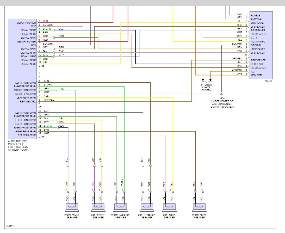
We have a sample Hyundai stereo wiring diagram available for download. This diagram will provide you with a visual reference to help you understand the concepts discussed in this article.
Note: Wiring diagrams can vary depending on the specific model year, trim level, and options package of your Hyundai. Always consult the correct diagram for your vehicle before starting any work.