Wiring Harness Mazda Wiring Diagram Color Codes
Understanding your Mazda's wiring harness is crucial for performing repairs, modifications, or even just understanding how its electrical systems operate. This article will guide you through interpreting Mazda wiring diagrams, specifically focusing on color codes and symbols. Think of this as your Rosetta Stone to deciphering the intricate language of your car's electrical system. We'll cover the purpose of these diagrams, key specifications, how to read them, and even some real-world troubleshooting tips. Plus, we'll emphasize safety precautions to keep you from getting shocked!
Purpose of the Mazda Wiring Diagram
Why bother learning about wiring diagrams? Several reasons:
- Diagnosis and Repair: Identifying faulty components like sensors, relays, or even damaged wires becomes significantly easier with a diagram. You can trace circuits to pinpoint the source of the problem.
- Modifications and Upgrades: Adding aftermarket accessories (stereos, lights, etc.) requires tapping into existing circuits. A wiring diagram shows you where to connect without causing damage or electrical shorts.
- Understanding System Operation: Even if you're not actively working on your car, understanding the wiring diagram helps you grasp how various systems (engine control, lighting, etc.) function.
- Avoiding Costly Repairs: Armed with knowledge, you can often perform basic repairs yourself, saving money on labor costs at a mechanic's shop.
Key Specs and Main Parts of a Wiring Diagram
Before diving into the specifics, let's outline the key elements you'll encounter in a typical Mazda wiring diagram:
- Component Symbols: Represent electrical parts like switches, relays, fuses, resistors, solenoids, and electronic control units (ECUs). These symbols are standardized, though slight variations might exist between different diagram providers.
- Wiring Lines: Solid lines represent wires, and their thickness usually (but not always) indicates wire gauge (thicker lines for higher current carrying capacity). Dashed lines may represent shielding or communication pathways.
- Color Codes: These are crucial! Each wire is identified by a color code, often a combination of two or three letters representing colors. More on this below.
- Ground Points: Indicated by a ground symbol, usually a series of downward-pointing triangles. These show where the circuit connects to the chassis for a return path.
- Connectors: Represented by various shapes, indicating the location where wires are joined together. The diagram often includes connector numbers or location references.
- Voltage Values: Sometimes, voltage values are indicated at specific points in the circuit, which are helpful for testing.
- Component Names and Circuit Numbers: Each component is labeled with a name and often a circuit number for easy identification.
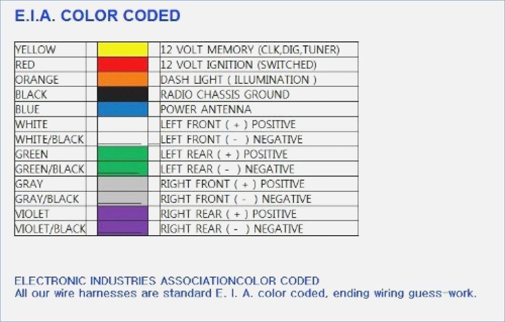
Decoding Mazda Wiring Diagram Color Codes
Mazda, like other manufacturers, uses a standardized color coding system for wires. Understanding this system is vital for identifying the correct wires to work with. Here's a breakdown of common color abbreviations:
Primary Colors:Secondary Colors (Stripes):
- B - Black
- R - Red
- W - White
- G - Green
- Y - Yellow
- L - Blue
- Br - Brown
- P - Pink
- O - Orange
- V - Violet (Purple)
- Gr - Gray
- Lt Gr - Light Green
So, a wire labeled "L/W" would be a Blue wire with a White stripe. "G/R" indicates a Green wire with a Red stripe. If you see three letters, the first letter is the main wire color, and the other two letters indicate the stripe colors (e.g., "W/R/B" is a White wire with Red and Black stripes).
Understanding Wiring Diagram Symbols
Wiring diagrams use standardized symbols to represent electrical components. Here's a brief overview of some common symbols:
- Resistor: A zig-zag line.
- Capacitor: Two parallel lines (sometimes curved).
- Inductor: A coiled line.
- Diode: A triangle pointing to a line.
- Transistor: Varies depending on the type (BJT, MOSFET), but generally involves a base, collector, and emitter (or gate, drain, and source).
- Switch: A line that can be opened or closed to complete or break a circuit.
- Relay: A coil that, when energized, closes a switch.
- Fuse: A wavy line inside a rectangle or a simple rectangle with a line through it.
- Ground: A series of downward-pointing triangles or a single triangle pointing downward.
- ECU: Usually a rectangular box labeled with its function (e.g., "PCM" for Powertrain Control Module).
How It Works: Tracing a Circuit
Let's say you want to trace the circuit for your Mazda's turn signals. Here's how you'd approach it using a wiring diagram:
- Locate the Turn Signal Circuit: Find the section of the wiring diagram related to the turn signals. This might be under "Lighting" or "Exterior Electrical."
- Identify the Power Source: Trace the circuit back to its power source, which is usually the battery, via a fuse or relay. Pay attention to the fuse rating!
- Follow the Wiring: Trace the wiring from the power source through the turn signal switch, flasher relay, and finally to the turn signal bulbs (front and rear). Note the color codes of the wires at each point.
- Identify Ground Points: Note where the circuit grounds to the chassis. A faulty ground can cause various electrical problems.
Real-World Use: Basic Troubleshooting Tips
Here are some troubleshooting tips using your newfound wiring diagram knowledge:
- No Power: If a circuit isn't working, start by checking the fuse. Use a multimeter to test if the fuse is blown (no continuity). If the fuse keeps blowing, there's likely a short circuit somewhere. The diagram will help you isolate potential short locations.
- Intermittent Problems: Intermittent issues can be tricky. Check connectors for corrosion or loose connections. Use the diagram to locate connectors in the affected circuit and inspect them carefully.
- Voltage Drops: Use a multimeter to measure voltage at various points in the circuit. A significant voltage drop indicates resistance, which could be caused by a corroded connector, damaged wire, or faulty component.
- Grounding Issues: A bad ground can cause all sorts of weird electrical problems. Inspect ground connections for corrosion or looseness. The wiring diagram shows the location of all ground points.
Safety Precautions
Working with automotive electrical systems can be dangerous. Always observe the following safety precautions:
- Disconnect the Battery: Before working on any electrical circuit, disconnect the negative battery terminal. This prevents accidental shorts and shocks.
- Use Proper Tools: Use insulated tools designed for automotive electrical work.
- Work in a Well-Lit Area: Ensure you have adequate lighting to see clearly.
- Avoid Water: Never work on electrical systems in wet conditions.
- High Voltage Components: Be extremely cautious around the ignition system, particularly the ignition coil(s). These components can generate high voltages that can be lethal. Avoid touching these components while the engine is running or the ignition is on.
- Airbag Systems: Disconnecting and reconnecting airbag systems requires specific procedures. Consult the vehicle's service manual to avoid accidental deployment.
By understanding Mazda wiring diagrams and color codes, you can confidently tackle a wide range of electrical repairs and modifications on your car. Remember to always prioritize safety and consult the service manual for specific procedures related to your vehicle model.
We have a comprehensive Mazda wiring diagram file available for download. It covers various models and years. Armed with this diagram and the knowledge gained in this article, you'll be well-equipped to diagnose and repair electrical issues on your Mazda.