Wiring Harness Nissan Stereo Wiring Diagram
Understanding the wiring harness for your Nissan stereo is crucial for a variety of reasons. Whether you're upgrading to an aftermarket head unit, diagnosing audio problems, adding amplifiers, or simply trying to understand how the factory system is wired, a reliable wiring diagram is your best friend. This article will break down a typical Nissan stereo wiring diagram, making it easier for you to navigate the often-complex world of automotive audio.
Purpose of a Nissan Stereo Wiring Diagram
A Nissan stereo wiring diagram serves several key purposes:
- Repairs: Identifying faulty wires or connections. If your speakers suddenly cut out or your head unit isn't powering on, the diagram helps you pinpoint the issue.
- Upgrades: Installing an aftermarket stereo or adding components like amplifiers and subwoofers. The diagram shows you where to tap into the factory wiring without cutting or splicing randomly.
- Troubleshooting: Diagnosing audio problems like distortion, static, or no sound. The diagram guides you in checking the continuity of circuits.
- Understanding the System: Simply understanding how the factory stereo system is designed and wired.
- Avoiding Damage: Connecting wires incorrectly can damage your head unit, speakers, or even your car's electrical system. The diagram helps you avoid these mistakes.
Key Specs and Main Parts of a Nissan Stereo Wiring Harness
Before diving into the diagram itself, let's define some key specifications and components:
- Voltage: Most Nissan stereo systems operate on a 12V DC (Direct Current) system, which is standard for automotive electrical systems.
- Impedance: Speaker impedance is usually 4 ohms. Connecting speakers with the wrong impedance can damage the head unit.
- Wire Gauge: The thickness of the wires matters. Thicker wires can carry more current. Common gauges in a stereo system include 16 AWG (American Wire Gauge) and 18 AWG for speakers, and thicker gauges (e.g., 12 AWG) for power and ground.
The main parts of a Nissan stereo wiring harness typically include:
- Head Unit Connector: This is the main connector that plugs into the back of the stereo. It contains all the power, ground, speaker, and control wires.
- Speaker Wires: These wires connect the head unit to the speakers. Each speaker has two wires: positive (+) and negative (-).
- Power Wire: Provides the main 12V power supply to the head unit. This is usually a constant 12V source.
- Ground Wire: Provides the return path for the electrical current. It's essential for proper operation.
- Accessory (ACC) Wire: Provides power to the head unit when the ignition is turned on. This wire prevents the head unit from draining the battery when the car is off.
- Illumination Wire: Dims the head unit's display when the headlights are turned on.
- Antenna Wire: Connects the head unit to the antenna for radio reception.
- Remote Turn-On Wire (or Amplifier Turn-On Wire): Used to turn on external amplifiers.
Understanding Symbols in a Nissan Stereo Wiring Diagram
Wiring diagrams use standardized symbols to represent electrical components and connections. Here's a breakdown of common symbols:
- Lines: Solid lines represent wires. The thickness of the line doesn't necessarily indicate wire gauge, but it can sometimes differentiate between power and signal wires.
- Colors: Each wire is assigned a specific color. These colors are crucial for identifying the correct wires in the harness. Common colors include:
- Red: Typically used for constant 12V power.
- Black: Typically used for ground.
- Yellow: Typically used for constant 12V power (sometimes interchangeable with red).
- Blue: Often used for the remote turn-on wire for amplifiers.
- Orange: Often used for the illumination wire.
- Speaker wires will typically be a solid color with a stripe of a different color (e.g., white with a black stripe).
- Connectors: Represented by various shapes, often rectangles or circles, with lines indicating the wires that connect to them.
- Ground Symbol: Usually a series of horizontal lines decreasing in length, indicating a connection to the vehicle's chassis (ground).
- Fuses: Represented by a wavy line inside a rectangle, indicating a protective device that breaks the circuit if the current exceeds a certain limit.
- Resistors: Represented by a zig-zag line.
- Capacitors: Represented by two parallel lines.
The wiring diagram will also contain abbreviations like "L" for left, "R" for right, "FR" for front right, "FL" for front left, "RR" for rear right, and "RL" for rear left. Understanding these abbreviations is crucial for identifying the correct speaker wires.
How a Nissan Stereo Wiring Harness Works
The Nissan stereo wiring harness is the central nervous system of your car's audio system. Here's a simplified explanation of how it works:
- Power Supply: The power wire (usually red or yellow) provides constant 12V power to the head unit, allowing it to retain memory (e.g., radio presets) even when the car is off. The ACC wire (accessory wire) provides power to the head unit when the ignition is turned on, enabling the head unit to operate.
- Grounding: The ground wire (usually black) provides the return path for the electrical current, completing the circuit. A good ground connection is essential for proper operation.
- Signal Processing: The head unit processes audio signals from various sources (e.g., radio, CD player, Bluetooth).
- Amplification: The head unit contains a built-in amplifier that boosts the audio signal to a level suitable for driving speakers.
- Speaker Output: The amplified audio signals are sent to the speakers through the speaker wires. Each speaker has a positive (+) and a negative (-) wire.
- Control Signals: The harness also carries control signals, such as the illumination wire, which dims the head unit's display when the headlights are turned on, and the remote turn-on wire, which activates external amplifiers.
Real-World Use: Basic Troubleshooting Tips
Here are some basic troubleshooting tips using a Nissan stereo wiring diagram:
- No Power to Head Unit: Use a multimeter to check for voltage on the power and ACC wires. If there's no voltage, check the fuses. Also, verify the ground connection is solid by checking continuity between the ground wire and the car's chassis.
- No Sound from Speakers: Check the speaker wire connections at the head unit and the speakers. Use a multimeter to check the continuity of the speaker wires. If a speaker wire is broken, replace it.
- Distorted Sound: Check the speaker impedance. Using speakers with the wrong impedance can damage the head unit. Also, check for short circuits in the speaker wires.
- Radio Not Working: Check the antenna wire connection. Make sure the antenna is properly connected to the head unit.
Safety Precautions
Working with automotive electrical systems can be dangerous. Here are some important safety precautions:
- Disconnect the Battery: Always disconnect the negative terminal of the battery before working on the electrical system. This will prevent accidental short circuits and electrical shocks.
- Use Proper Tools: Use insulated tools to prevent short circuits.
- Avoid Cutting Wires: Whenever possible, use wire taps or connectors instead of cutting and splicing wires. This will make it easier to undo your modifications if necessary.
- Be Careful with Airbags: Airbags are electrically triggered. Avoid working near airbag components unless you know what you're doing. Accidental deployment can cause serious injury.
- Fuses Protect: Never replace a fuse with one that has a higher amperage rating. This can overload the circuit and cause a fire.
Warning: The airbag system and the anti-lock braking system (ABS) are particularly sensitive and potentially dangerous. If you're not comfortable working with these systems, consult a qualified technician.
By understanding the wiring diagram and following these safety precautions, you can safely and effectively work on your Nissan stereo system. This guide provides a solid foundation for understanding and troubleshooting common issues. Armed with this knowledge, you're well-equipped to tackle most stereo-related projects on your Nissan.
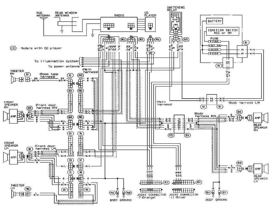
We have a sample Nissan stereo wiring diagram available for download. This diagram provides a visual representation of the wiring harness and can be a valuable tool for your projects. Please note that specific wiring configurations may vary depending on the year, model, and trim level of your Nissan vehicle.